Built Around Your Process

Inclined Screw Conveyor

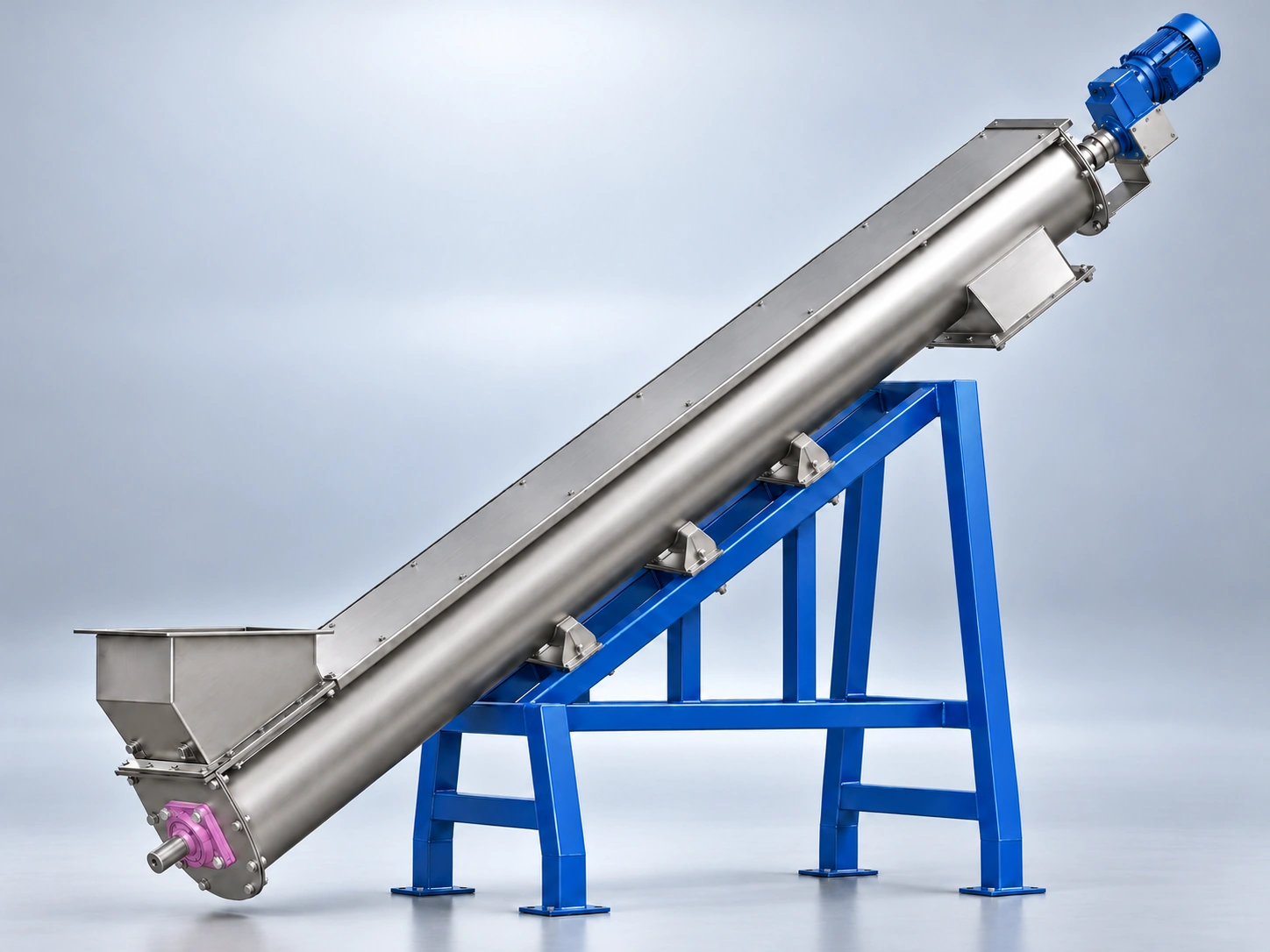
Designed for bulk material conveying on an incline, with screw geometry, speed, feed arrangement and power selected for angle, lift and material behavior.

Inclined Screw Conveyor
Inclined Screw Conveyor working principle
Understand the Configuration

How It Works

An inclined screw conveyor moves bulk material upward along an angled route. As the incline increases, gravity acts more strongly against forward material movement, increasing the tendency for material to fall back between the screw flights and reducing effective conveying capacity. Screw pitch, speed, diameter, loading and power are therefore selected for the actual incline, elevation gain and material behavior rather than applying horizontal conveyor performance unchanged. Feed arrangement, housing form, drive position and structural support are then coordinated around the required route.
01

Capacity Effect

Effective conveying capacity decreases as incline increases, so horizontal-duty ratings should not be applied unchanged.

02

Fallback Control

Screw geometry, speed, housing and material behavior determine how effectively backward movement between flights can be controlled.

03

Feed Stability

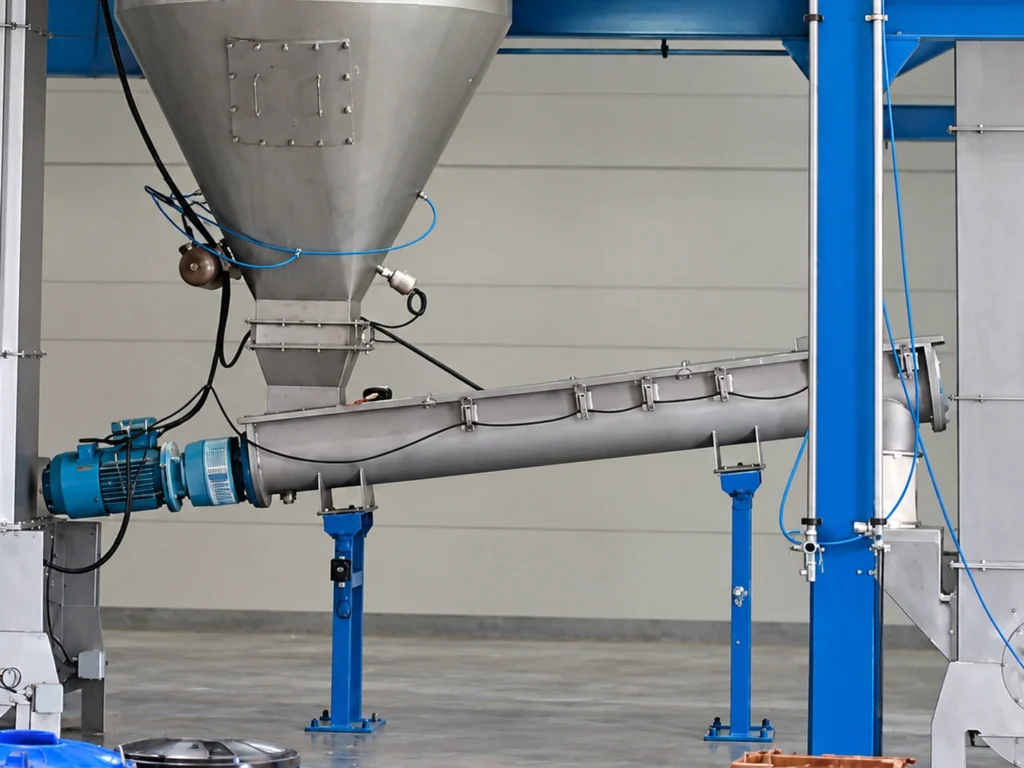
Controlled feeding at the lower end helps prevent surging, local overfilling and unstable conveying on the incline.

Choose Around Your Application

Your Options

These are the main configuration decisions. Material, capacity, layout and operating conditions determine which combination fits the application.

01

Housing Form

Housing form is selected according to incline angle, material containment, fallback behavior and maintenance access.

Compare Choices
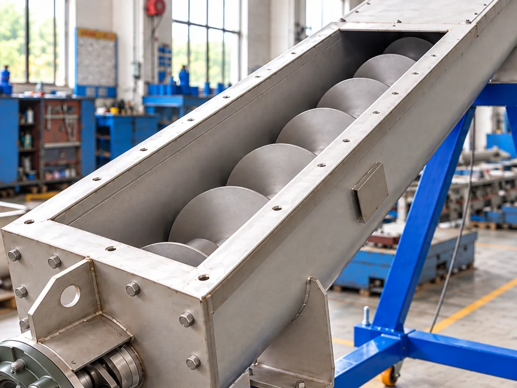
U-Trough Housing

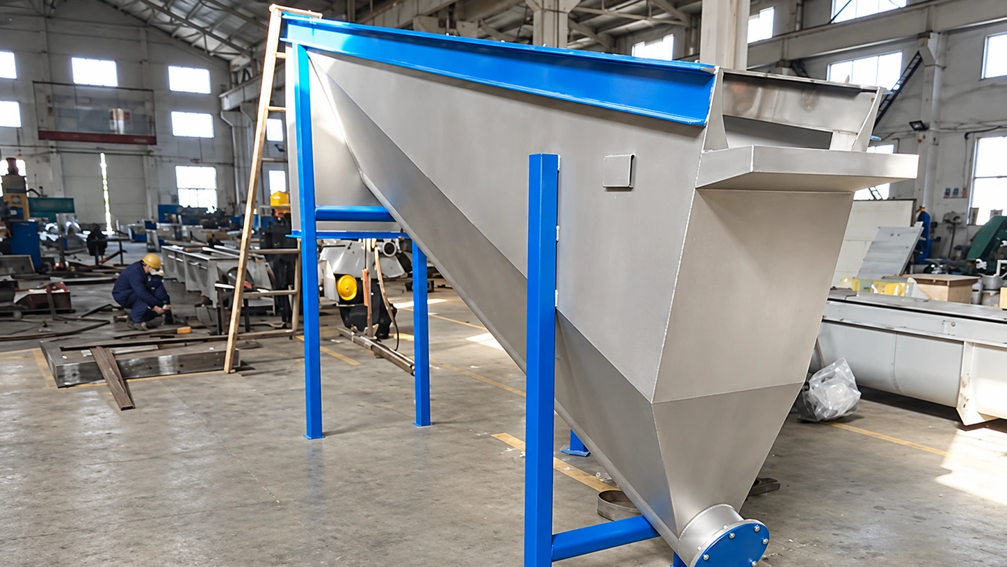
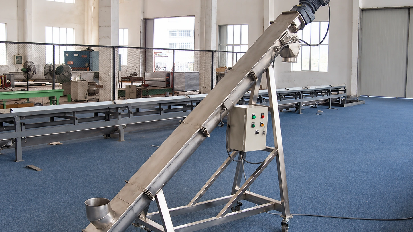
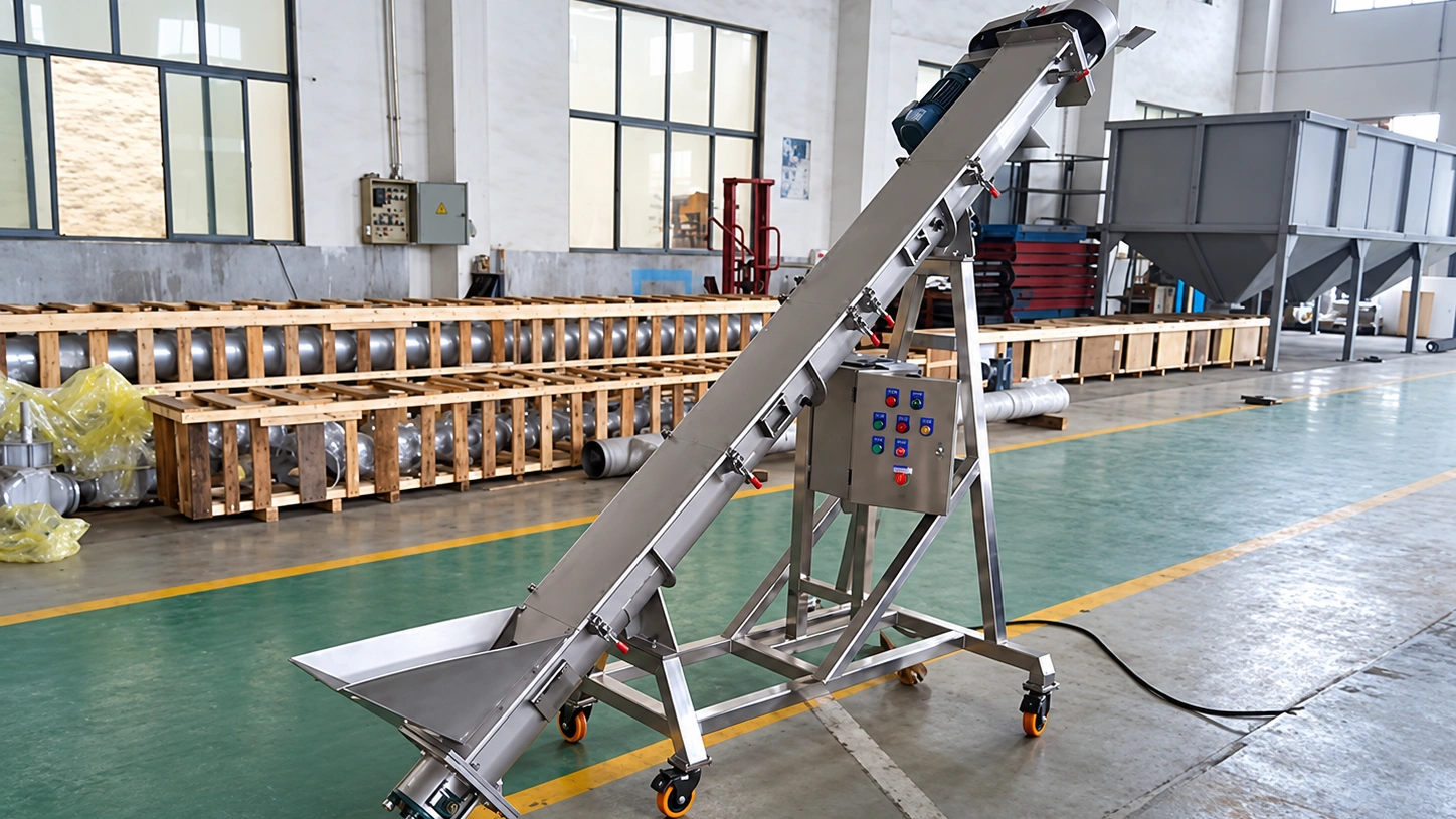
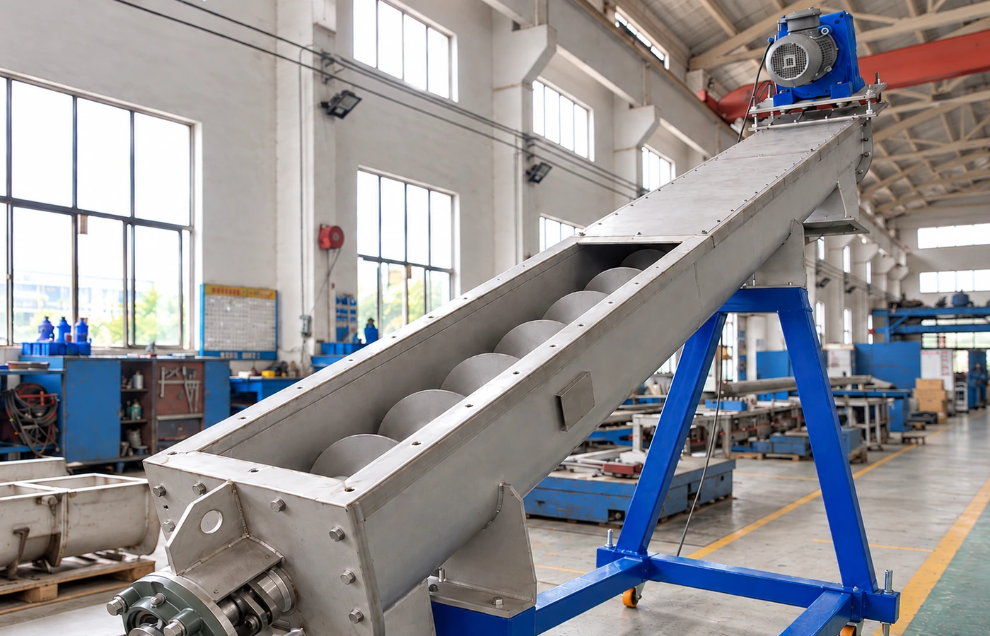
Provides accessible conveying and maintenance where the incline and material behavior allow a trough configuration.

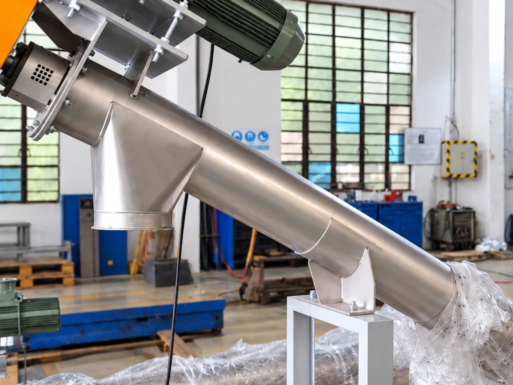
Tubular Housing

Provides full enclosure and greater material containment where incline, dust control or process conditions favor a closed housing.
02

Flight Geometry

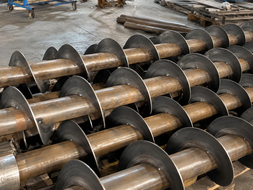
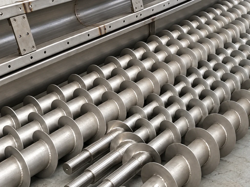
Flight pitch and geometry are selected to maintain controlled forward material movement as the incline increases.

Compare Choices
Standard-Pitch Flight

Used where incline and material behavior allow stable conveying with conventional flight geometry.

Reduced-Pitch Flight

A shorter pitch can improve material control where increased incline makes fallback more significant.

03

Support & Installation

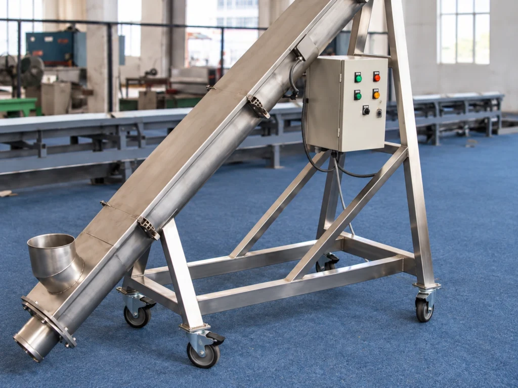
Support arrangement is selected according to conveyor angle, installation conditions, equipment load, and whether the conveyor needs to be repositioned.

Compare Choices
Fixed Support Installation

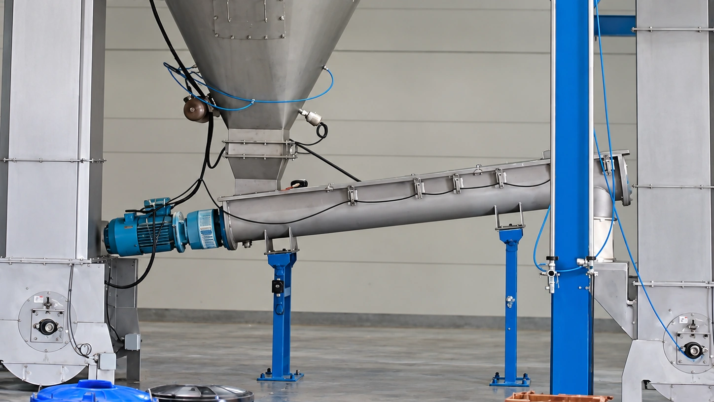
The conveyor is permanently supported from the floor or existing structural steel to maintain stable positioning and alignment during operation.

Mobile Support Frame

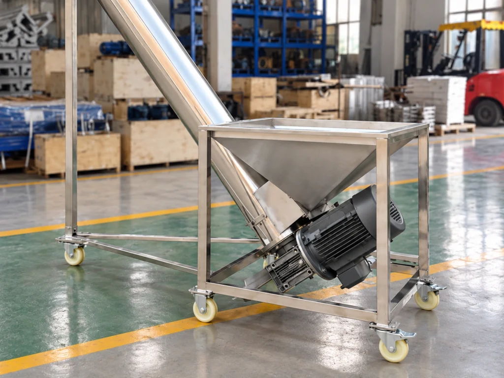
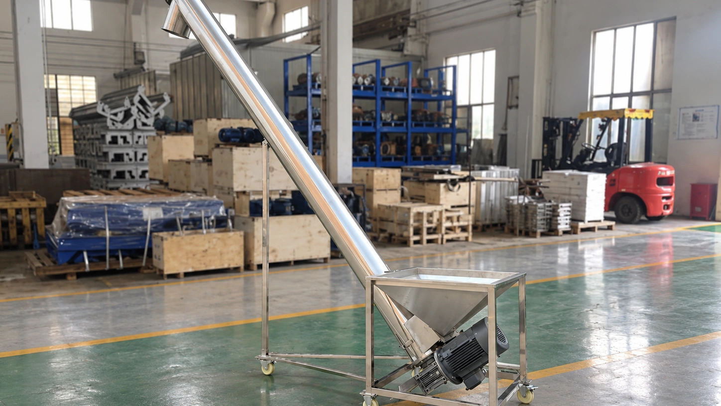
The conveyor is mounted on a dedicated movable frame where repositioning or flexible installation is required.

04

Drive Arrangement

Drive position is selected around the inclined load path, required torque, maintenance access and surrounding equipment.

Compare Choices
Head-End Drive

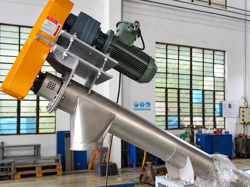
Positions the drive at the upper discharge end, keeping the screw assembly under a pulling load during conveying.

Bottom-End Drive

Positions the drive at the lower feed end where equipment layout or maintenance access favors this arrangement, subject to shaft loading, thrust, and drive checks.

Technical Inquiry

Start Here

Tell us what you are moving and what the process needs to achieve. We will review the application and follow up on the technical details that matter.

Material: What are you conveying?
Capacity: What throughput do you need?
Layout: Approximate length, inclination or known connection points.
Project Details: Add anything that may affect the application.
Attachments: Share with us docs like drawing, photos, flow chart if available.

Prefer a quick conversation?

Message us on WhatsApp

Project Details

No commitment required. We evaluate application feasibility first.

We will review the application before recommending a conveyor configuration.