Built Around Your Process

U-Trough Screw Conveyor

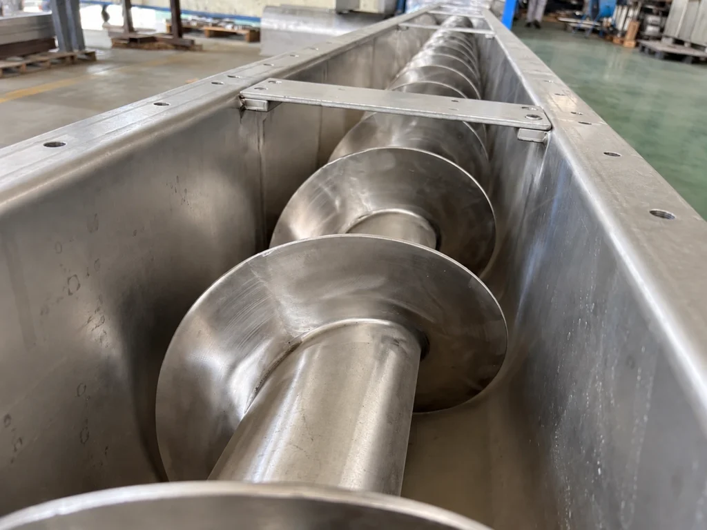
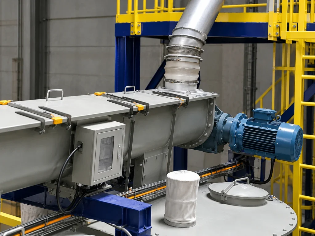
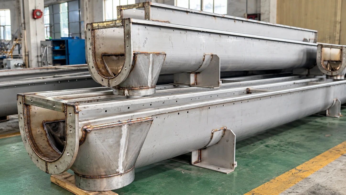
A U-trough configuration for applications where inspection, cleaning and maintenance access matter alongside enclosed conveying and plant layout requirements.

U-Trough Screw Conveyor
U-Trough Screw Conveyor working principle
Understand the Configuration

How It Works

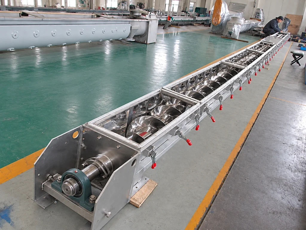
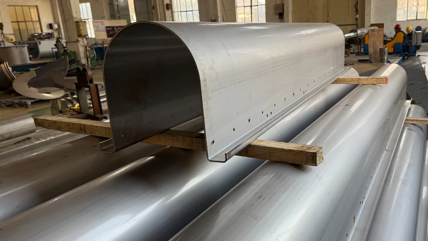
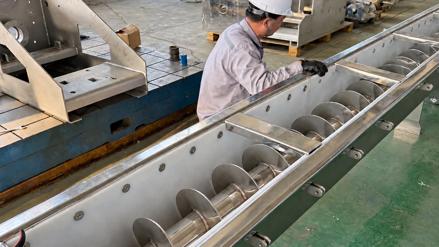
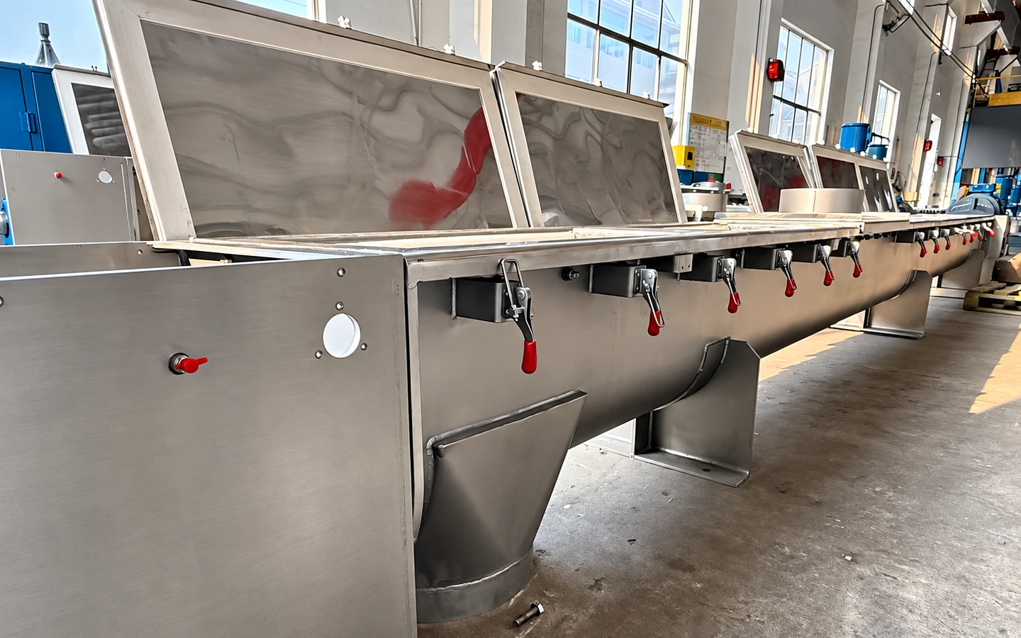
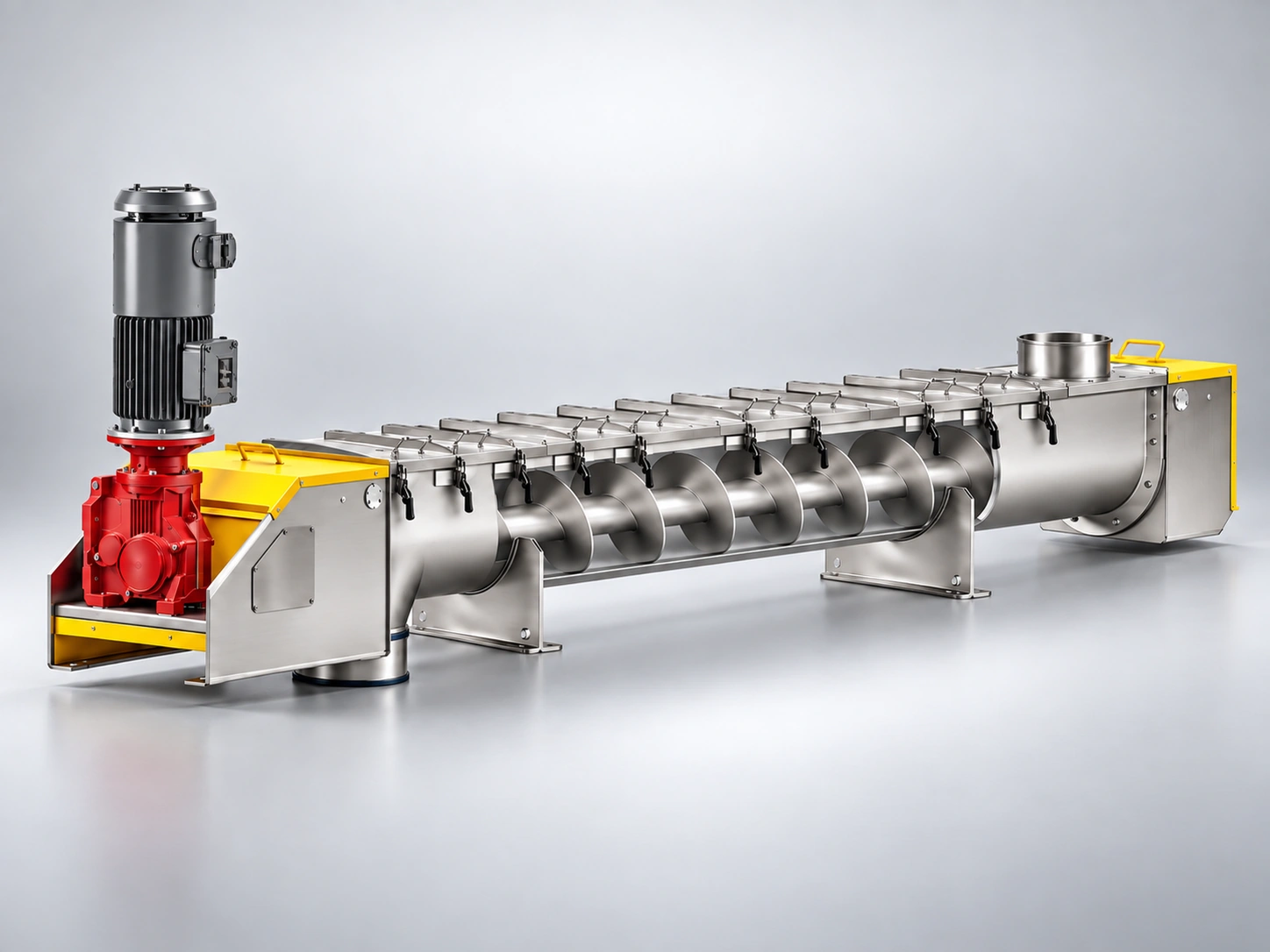
Material is moved through a U-shaped trough by a rotating screw. Removable covers provide access to the conveying section, screw and material path for inspection, cleaning or maintenance when required. The trough shape is only the starting point. Screw arrangement, shafting, covers, inlet and discharge interfaces, section length and material of construction are selected around the conveyed material, required capacity, access needs and plant layout.
01

Open Trough

Removable covers give direct access to the conveying section when inspection, cleaning or maintenance is required.

02

Flexible Access

Cover sections, inspection points and plant interfaces can be arranged around the access your process and maintenance routine require.

03

System Fit

Trough geometry, screw clearance, supports and connection points are coordinated to fit the surrounding equipment and required interfaces.

Choose Around Your Application

Your Options

These are the main configuration decisions. Material, capacity, layout and operating conditions determine which combination fits the application.

01

Cover Design

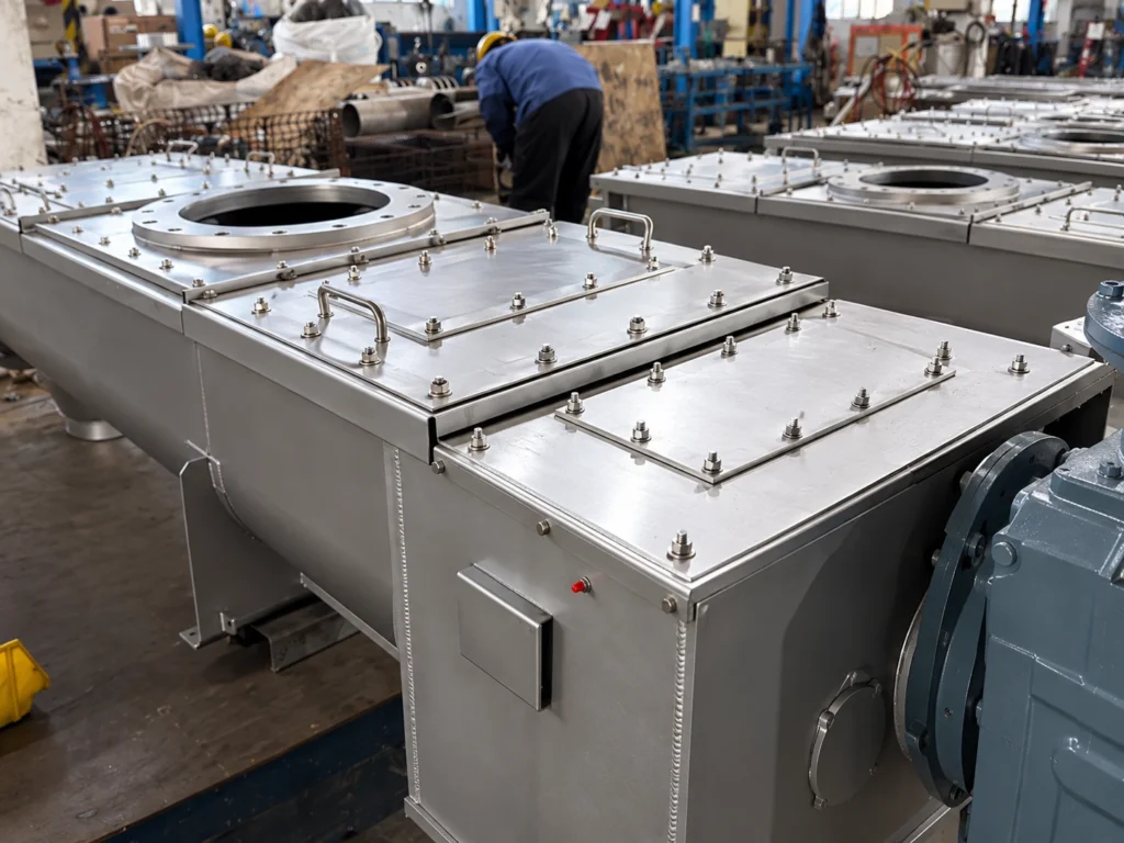
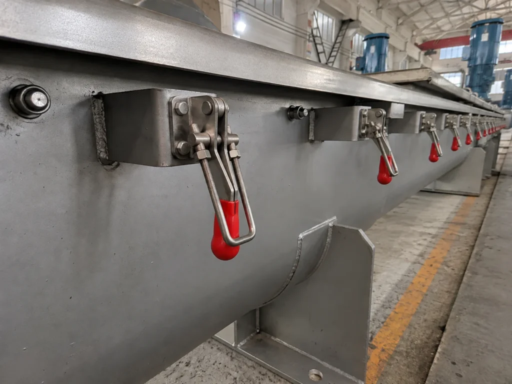
Cover arrangement is selected around containment needs and how often the conveyor needs to be opened for inspection or cleaning.

Compare Choices
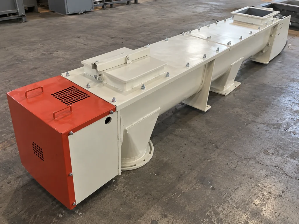
Bolted Cover

A straightforward enclosed arrangement where frequent opening is not the main requirement.

Clamped Cover

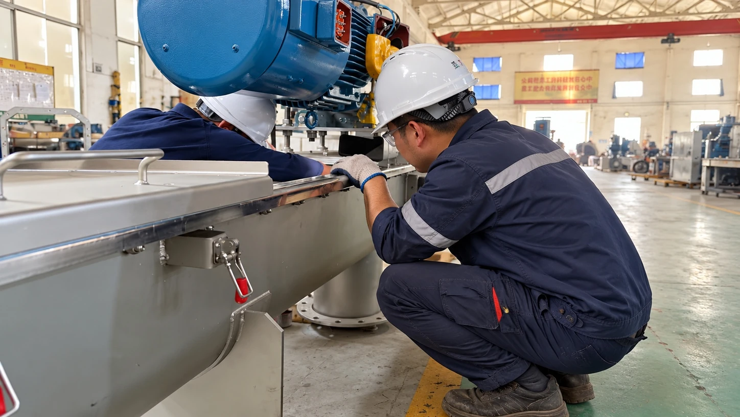
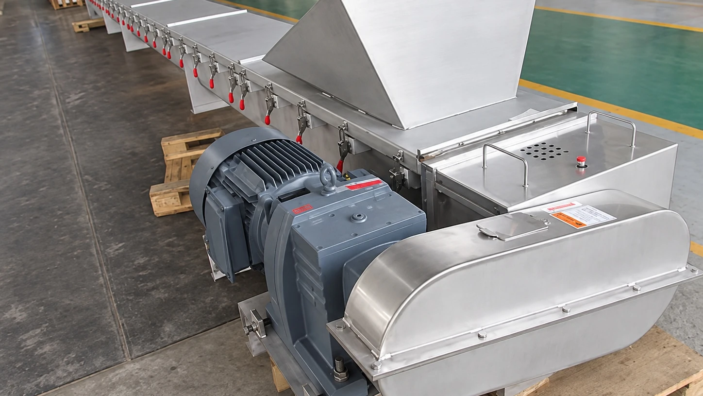
Quick clamps provide faster access where the trough needs to be opened more often for inspection or cleaning.
02

Screw Arrangement

Screw arrangement is selected around material behavior, conveying duty and whether the application is better suited to a supported shaft or an open-center spiral.

Compare Choices
Shafted Screw

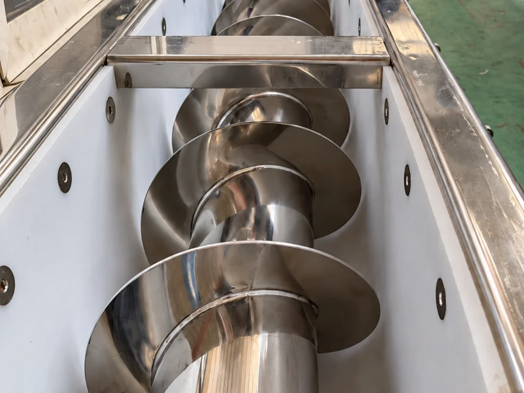
Uses a center shaft and support arrangement where a conventional supported screw is suitable for the duty.

Shaftless Screw

Uses a shaftless spiral with an open center where material behavior or process requirements favor that arrangement.

03

Flight Design

Flight geometry is selected around material behavior and whether the application needs straightforward conveying, a more open flow path or additional agitation during conveying.

Compare Choices
Standard Flight

Continuous flighting for general conveying where the material flows consistently and no special agitation is required.

Ribbon Flight

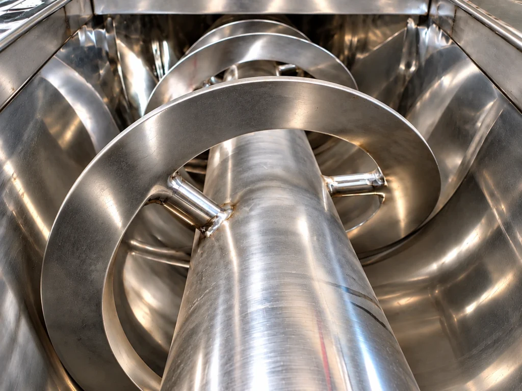
An open-center ribbon profile provides more open space around the screw center and can suit sticky, cohesive or build-up-prone materials.

Cut / Notched Flight

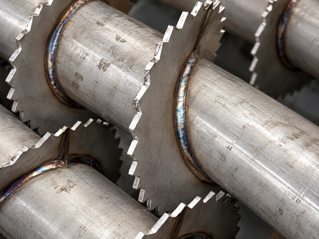
Interrupted or notched flight edges add material disturbance and can help break soft agglomerates while conveying.

04

Plant Interfaces

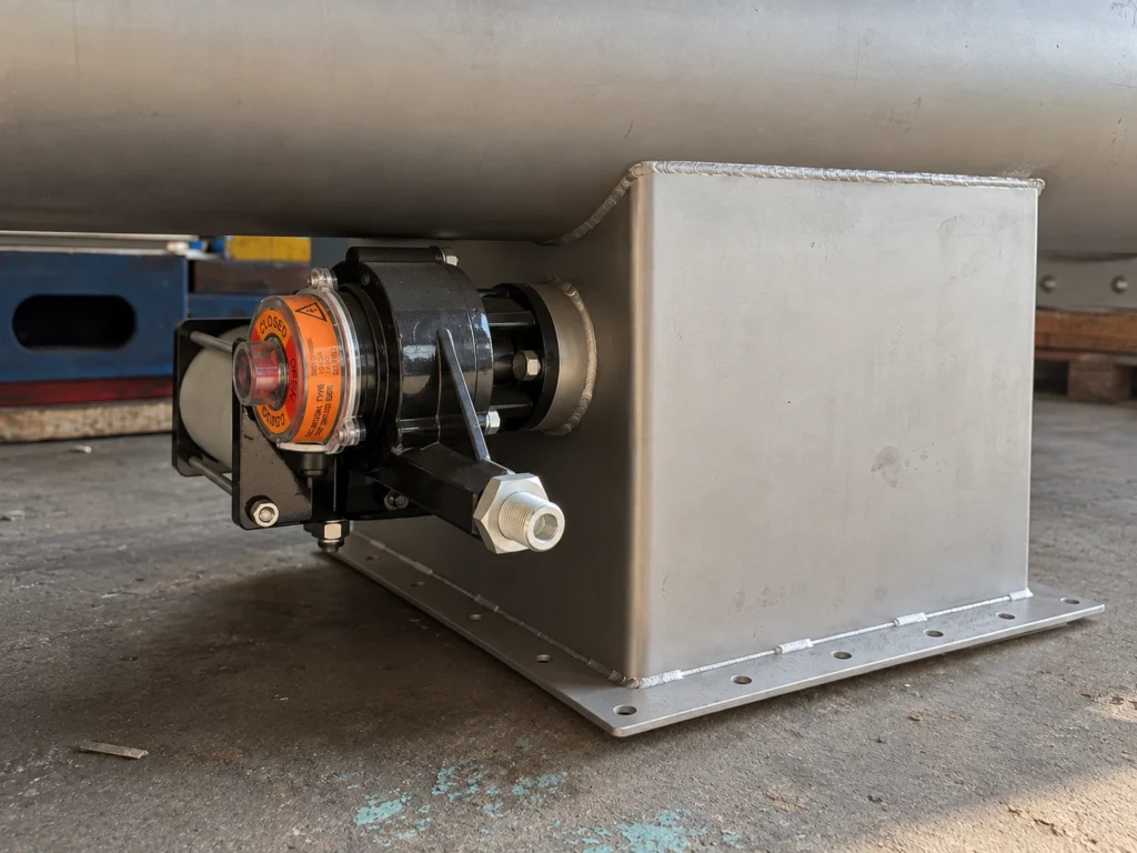
Inlet and discharge geometry are coordinated with the upstream equipment, downstream equipment and required material flow path.

Compare Choices
Feed Interface

Inlet size and position are matched to the upstream feed point and available layout.

Discharge Interface

Outlet size, position and geometry are arranged around the downstream connection and material path.

05

Drive Arrangement

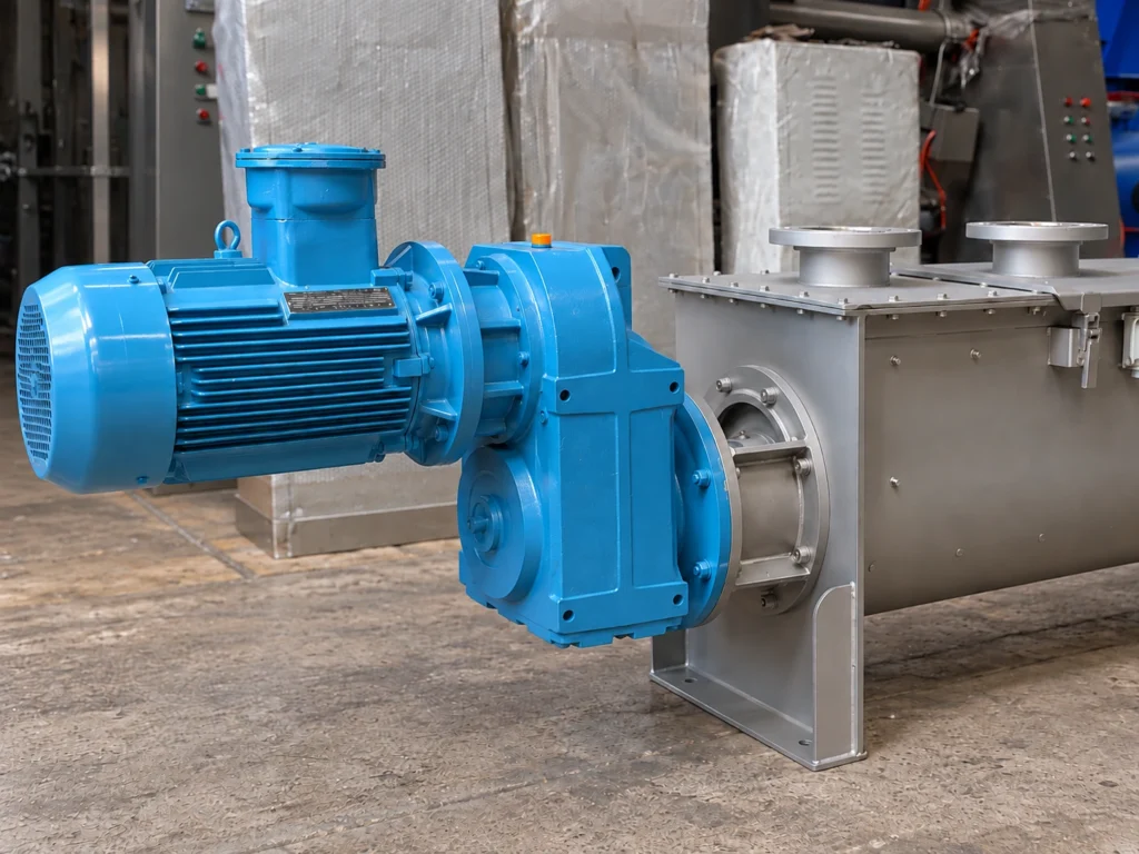
Drive arrangement is selected around available space, shaft connection, maintenance access and the mechanical layout of the conveyor.

Compare Choices
Direct Drive

A compact arrangement where the gearbox output connects directly to the conveyor shaft, minimizing intermediate transmission components.

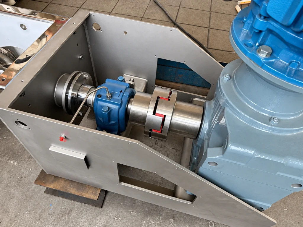
Coupling Drive

A flexible coupling connects the drive and conveyor shaft, providing a defined connection point for alignment, assembly and maintenance.

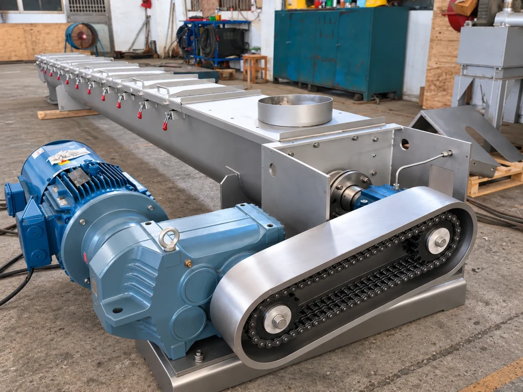
Chain & Sprocket

Chain transmission allows the drive to be offset from the screw shaft where space, layout or transmission arrangement makes an inline drive less suitable.

06

Construction Material

Material of construction is selected around product contact, corrosion exposure, cleaning requirements and the operating environment.

Compare Choices
Carbon Steel

Used where carbon steel is compatible with the conveyed material and service environment.

Stainless Steel

Used where corrosion resistance, cleaning or product-contact requirements call for stainless steel.

Technical Inquiry

Start Here

Tell us what you are moving and what the process needs to achieve. We will review the application and follow up on the technical details that matter.

Material: What are you conveying?
Capacity: What throughput do you need?
Layout: Approximate length, inclination or known connection points.
Project Details: Add anything that may affect the application.
Attachments: Share with us docs like drawing, photos, flow chart if available.

Prefer a quick conversation?

Message us on WhatsApp

Project Details

No commitment required. We evaluate application feasibility first.

We will review the application before recommending a conveyor configuration.